
Have you ever ever wished to construct your individual telephone from scratch? Ideally on essentially the most ubiquitous electronics prototyping platform for max flexibility and minimal ergonomics? Now you’ll be able to!

In our latest product showcase video overlaying the brand new SparkFun LTE Stick – LARA-R6, I confirmed off a undertaking of mine that makes use of the LTE Stick in a enjoyable manner; I name it the Breadboard Telephone!
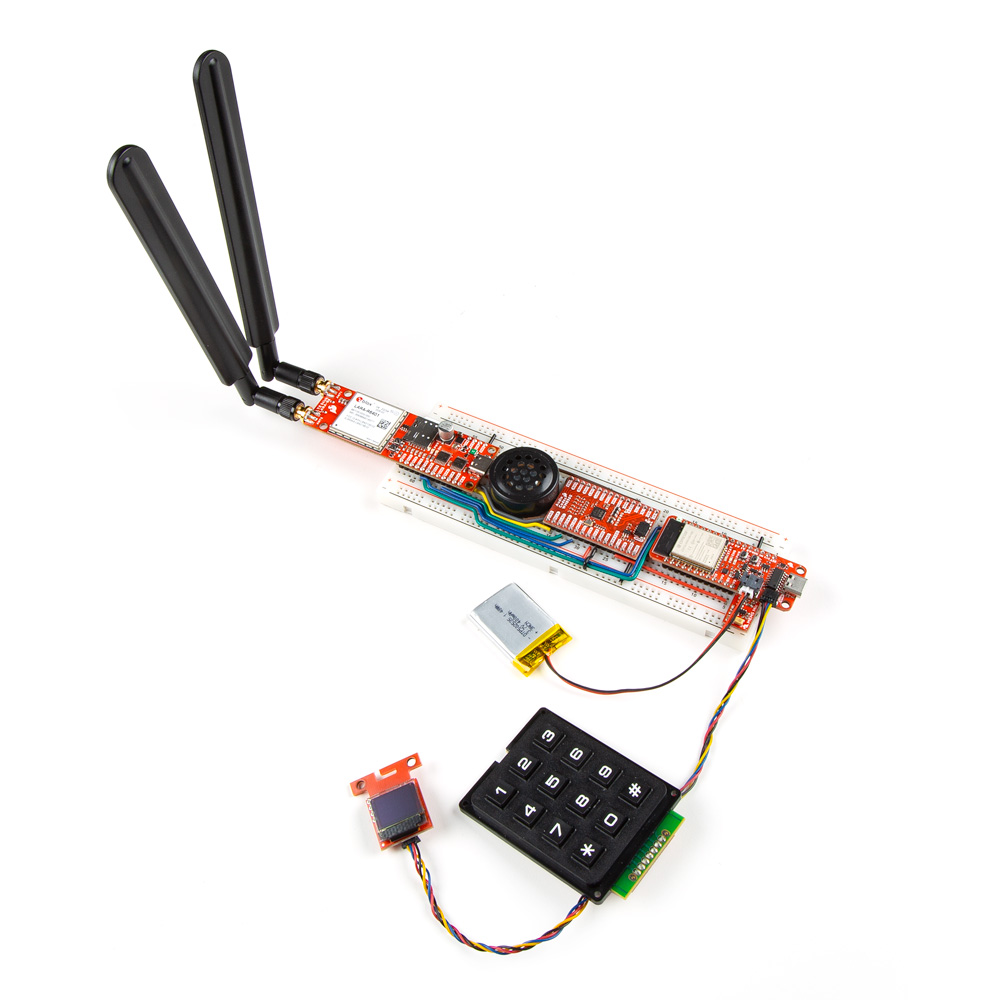
For anybody who hasn’t seen the video, bounce to eight minutes into the video to see it in motion!
On this submit, I am going to stroll you thru find out how to construct a Breadboard Telephone of your individual! Although a fast head up earlier than we dive in – that is under no circumstances an entire undertaking! This was actually simply meant to be a enjoyable demo of the LTE Stick, so not every thing has been thought by utterly, and the software program has some tough edges and lacking options. So you may have to do some work should you really need this to perform effectively.
Required Supplies
Firstly, you may want an LTE Stick! That was the unique motivation for this undertaking, proper? Remember to get a pair LTE antennas too! And you may want a SIM card to hook up with a community with a plan that features the options you need; discovering an acceptable SIM card is arguably essentially the most tough step. As an example, the Hologram SIM card we promote is de facto solely meant for knowledge; sending texts will be hit and miss, and it would not assist telephone calls. We bough a Cricket SIM card that labored fantastic in my telephone, however they suspended service after inserting it into the LTE Persist with a textual content message saying it is an “unsupported system” even supposing it labored fantastic for the two minutes earlier than they stopped the service… I ended up utilizing my private SIM card (service is Ting) and that labored completely fantastic.
Second, you may want a microcontroller to deal with all the principle logic of interfacing with the person inputs/outputs and telling the LTE Stick what to do. You do not really want something particular or fancy for this, I simply selected the ESP32 Factor Plus as a result of I had one mendacity round on my desk. Nevertheless as a result of its pretty highly effective and has built-in WiFi and Bluetooth, that leaves numerous room for enlargement with this undertaking!
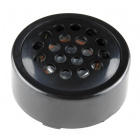
Subsequent, you may want a approach to enter and output audio. The LTE Stick has I2S audio pins damaged out to PTH headers particularly for this goal, and is meant to hook up with an audio codec. For this, I used the WM8960 audio codec that Pete made a few yr in the past, and it really works nice for this software! As well as, you may want a microphone and a speaker to truly measure and create sound waves. I used the SPH8878LR5H-1 MEMS Microphone for its small kind issue that may sit proper subsequent to the Factor Plus on the finish of the breadboard, and this PCB mount speaker which simply barely squeezes into the area remaining on the breadboard.
You will want a pair elements for person enter and output. In fact, I used the Qwiic Keypad for person enter – how may you not use that for a telephone undertaking! And for displaying stuff to the person, I used our Qwiic Micro OLED. In hindsight, this was most likely not the most effective resolution, the display screen is de facto too small for this undertaking. I simply grabbed it early on whereas prototyping, and the undertaking grew with it, so it turned an excessive amount of effort for me to hassle refactoring what was wanted to make use of an even bigger show. When you’re utilizing Qwiic elements, remember some Qwiic cables!
Oh, and if you wish to battery energy this undertaking, you may want a LiPo battery as effectively! I wasn’t too nervous about working period, so I arbitrarily picked this 400mAh battery, however you’ll be able to at all times go greater if you’d like it to run for longer!

Lastly, you may want elements to place every thing collectively. You may clearly do that nevertheless you want, however as somebody who’s a bit too captivated with breadboards, I in fact needed to stick every thing right into a breadboard. When you select to go down that route, you may additionally want wires to attach every thing. You may use regular breadboard jumper wires, however 22AWG stable core hookup wire is de facto really helpful right here; you may additionally want instruments to lower and strip the wires. And a few soldering shall be required to connect headers to the boards, so you may want an iron and solder.
And this is all these elements in a single want checklist in case you need to add all of them to cart with a single click on!
Meeting Information
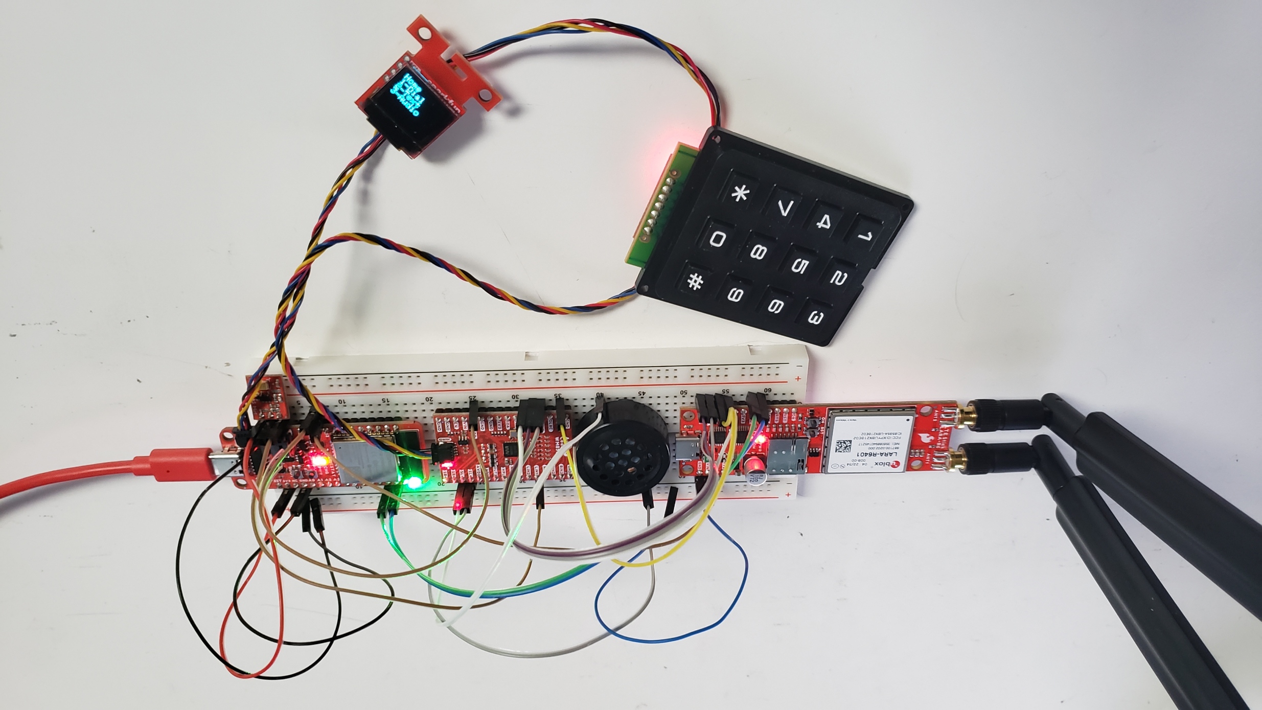
Proper, let’s dive into the meeting! Like talked about above, you need to use regular breadboard jumpers if you want, and that is what I did to start with! Nevertheless this undertaking requires a number of wires, so it will get messy fairly shortly, and full measurement jumper forestall you from having the ability to maintain the telephone subsequent to your head correctly. That is the mess I used to be coping with!
So I undoubtedly suggest making customized jumper wires which are the precise size wanted for every section. That is one thing I picked up from Ben Eater, who makes implausible pc engineering movies on YouTube! This video of his provides a superb rationalization of the method. The TLDW is to make use of 22AWG stable core wire, and bend it into the form you want with an additional 0.3″ at every finish to strip the insulation from to insert into the breadboard rails.
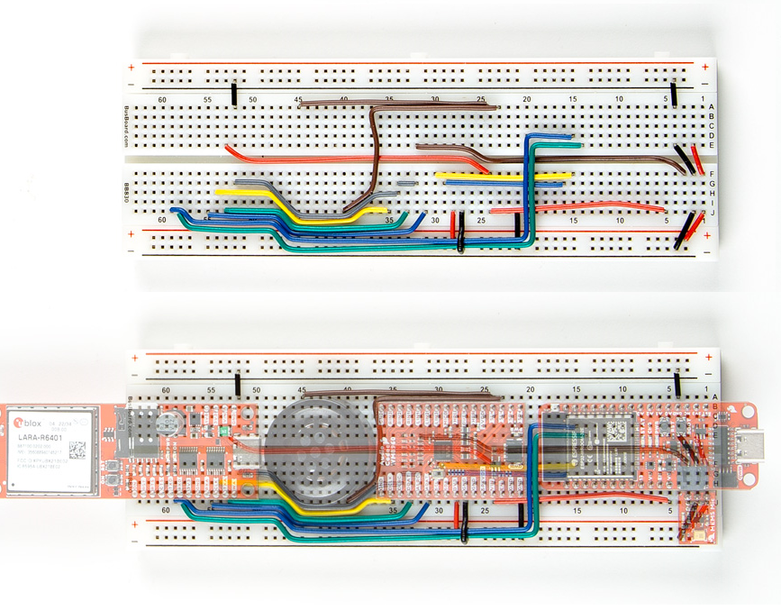
Beneath is a closeup of the breadboard I used with all of the elements eliminated so you’ll be able to see precisely the place every wire goes. Beneath that, we have additionally overlayed the elements so you’ll be able to see precisely what pin every wire is supposed to connecto to. Observe that some wires go below elements as a way to make it look a bit neater.
One thing else to notice – you may want to decide on find out how to energy some elements. I used the three.3V pin coming from the Factor Plus board to energy the microphone and digital IO pin of the audio codec, however the speaker and LTE Stick require a bit extra voltage/energy than the three.3V pin can provide. As a result of I need this undertaking to be transportable, I used the VBAT pin on the Factor Plus, which connects on to the LiPo battery. The restriction right here is that it’s essential to have a battery plugged in for the LTE stick to truly activate correctly. Another answer is to make use of the VUSB pin, which connects on to the USB connector on the Factor Plus; the draw back right here is that it will not be transportable.
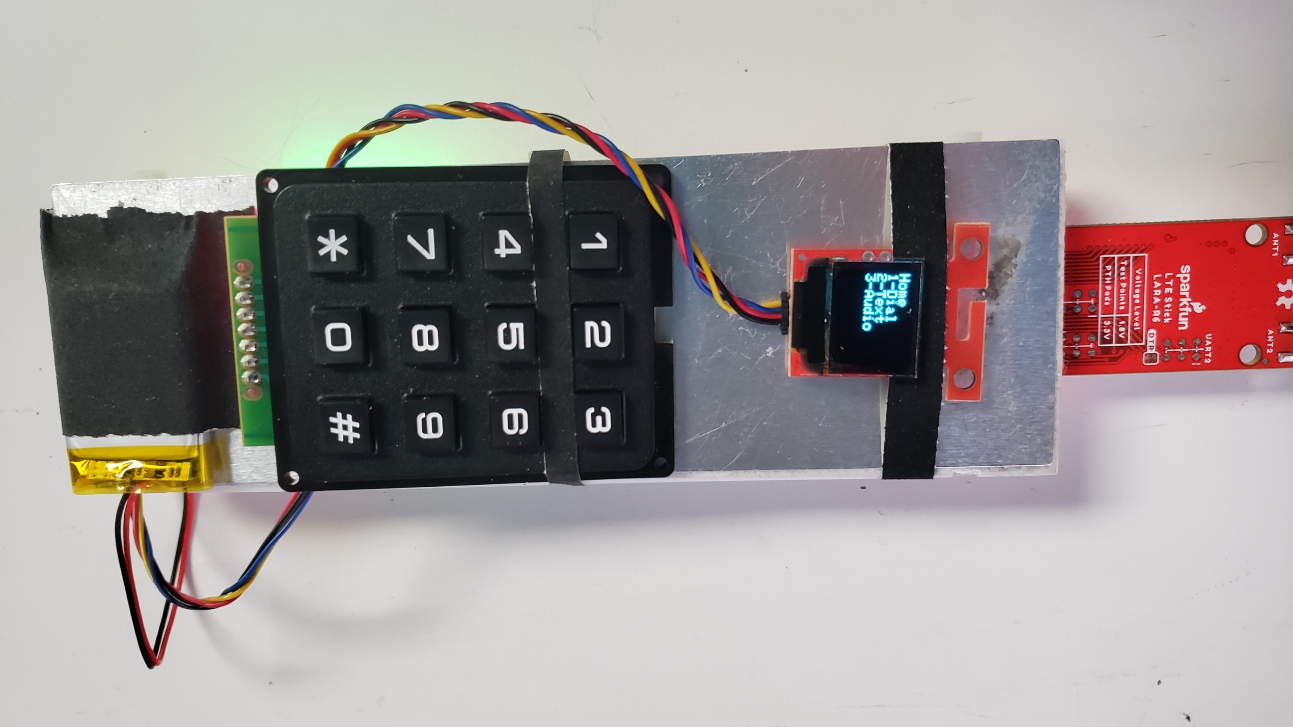
As soon as the breadboard is all wired up, the final step of the meeting is to insert your SIM card, join the keypad and show with a pair Qwiic cables, and join the battery. Sadly there’s actually no extra room on the breadboard for these to go, so I simply taped them onto the again of the breadboard.
It isn’t essentially the most elegant answer, I do know; I simply ran out of time to do one thing higher. One enjoyable suggestion I heard was so as to add these elements onto a second breadboard, then join each breadboards with a hinge to create a Breadboard Flip Telephone! I really like the concept, but it surely’s sadly past what I’ve time for now.
And that is all for the {hardware} meeting! When you determine to recreate this undertaking, I might love to listen to should you improved on this!
Software program
The final main step is to flash the code onto the microcontroller. All of the code I wrote is written in Arduino and saved within the GitHub repo for the LTE Stick, so you’ll be able to simply obtain it and flash it onto your board. It does rely upon our new u-blox Mobile Arduino Library, so you may want so as to add that earlier than you’ll be able to compile and add the code.
Some options are additionally particular to the ESP32 Factor Plus, so should you’re utilizing a special growth board, chances are you’ll have to make some adjustments there. And as I discussed at first of this submit, this undertaking was initially solely meant to be a demo of a enjoyable manner to make use of the LTE Stick relatively than a ultimate undertaking, so the code is under no circumstances excellent. I have never applied an entire lot of options, it is in no way optimized, and it would not deal with all the sting circumstances. It is actually only a proof-of-concept to show the undertaking and it is not prepared for prime time, so you may most likely need to add some code of your individual to get it working higher.
Utilization
And that is it! Energy it up, ensure that to press the ON button on the LTE Stick, and the code will examine that every thing is linked. Throughout this time, it should use the OLED show and the RGB LED on the Factor Plus to present standing info, in addition to printing debug messages over Serial in case you want that. This is what it reveals throughout startup:
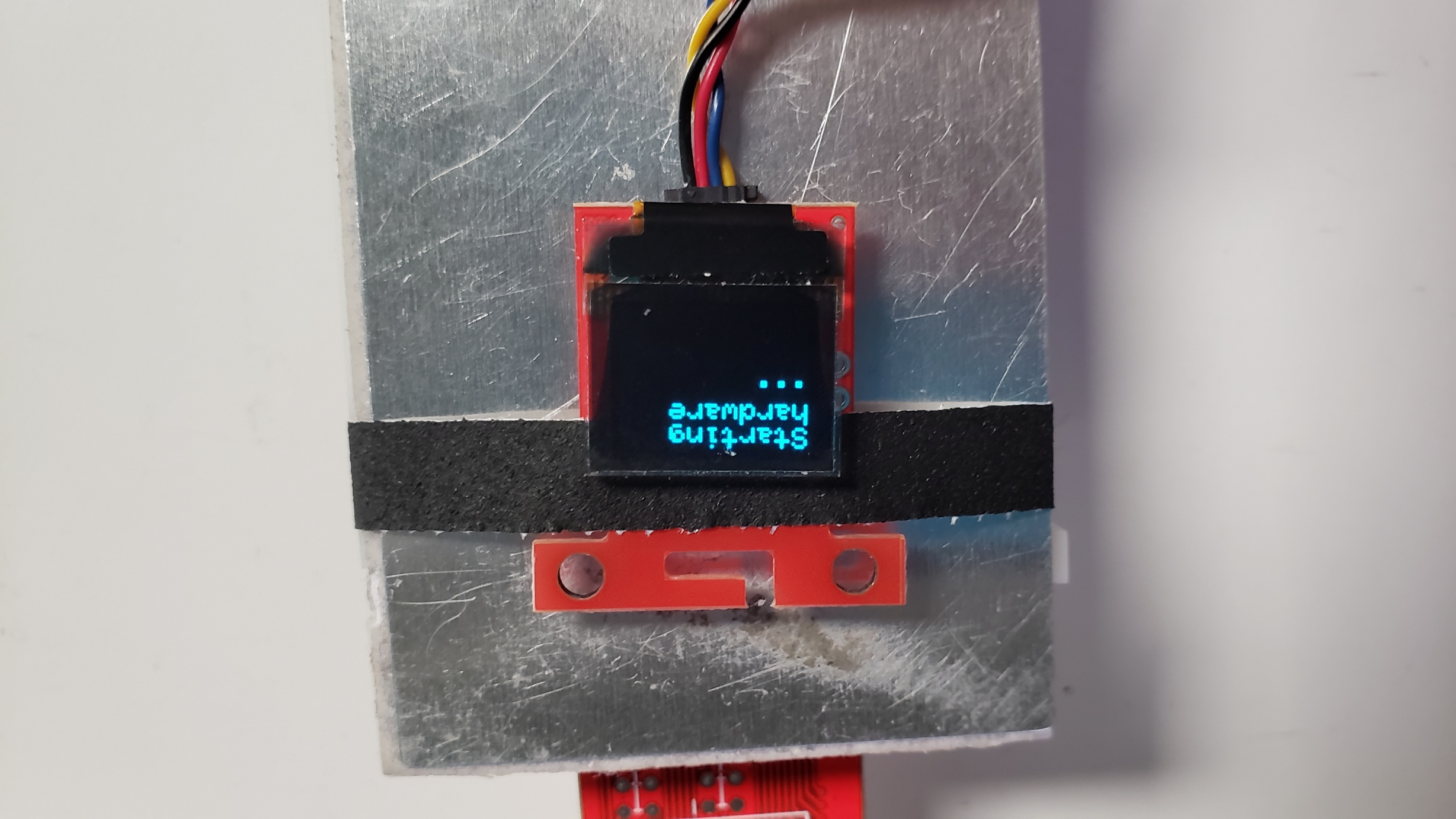
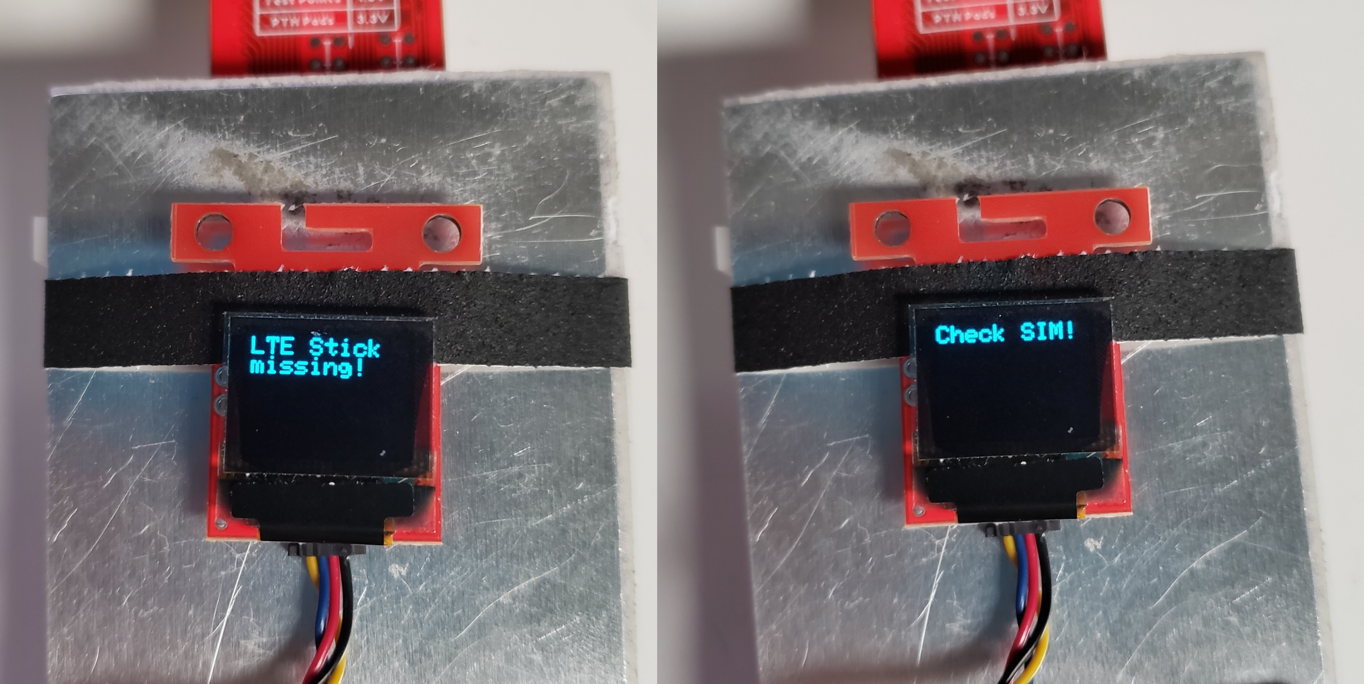
The RGB LED shall be blue throughout begin up, and alter to inexperienced if profitable, or crimson if there’s a difficulty detected. If the OLED is working, a message shall be displayed on it indicating the precise drawback. For instance, should you neglect to press the ON button on the LTE Stick or neglect the SIM card, it should show considered one of these messages on the OLED:
When you’re operating into bother, double examine the wiring and take a look at operating among the examples from the SparkFun u-blox Mobile Arduino Library. Assuming all goes effectively, the principle menu shall be displayed on the OLED.
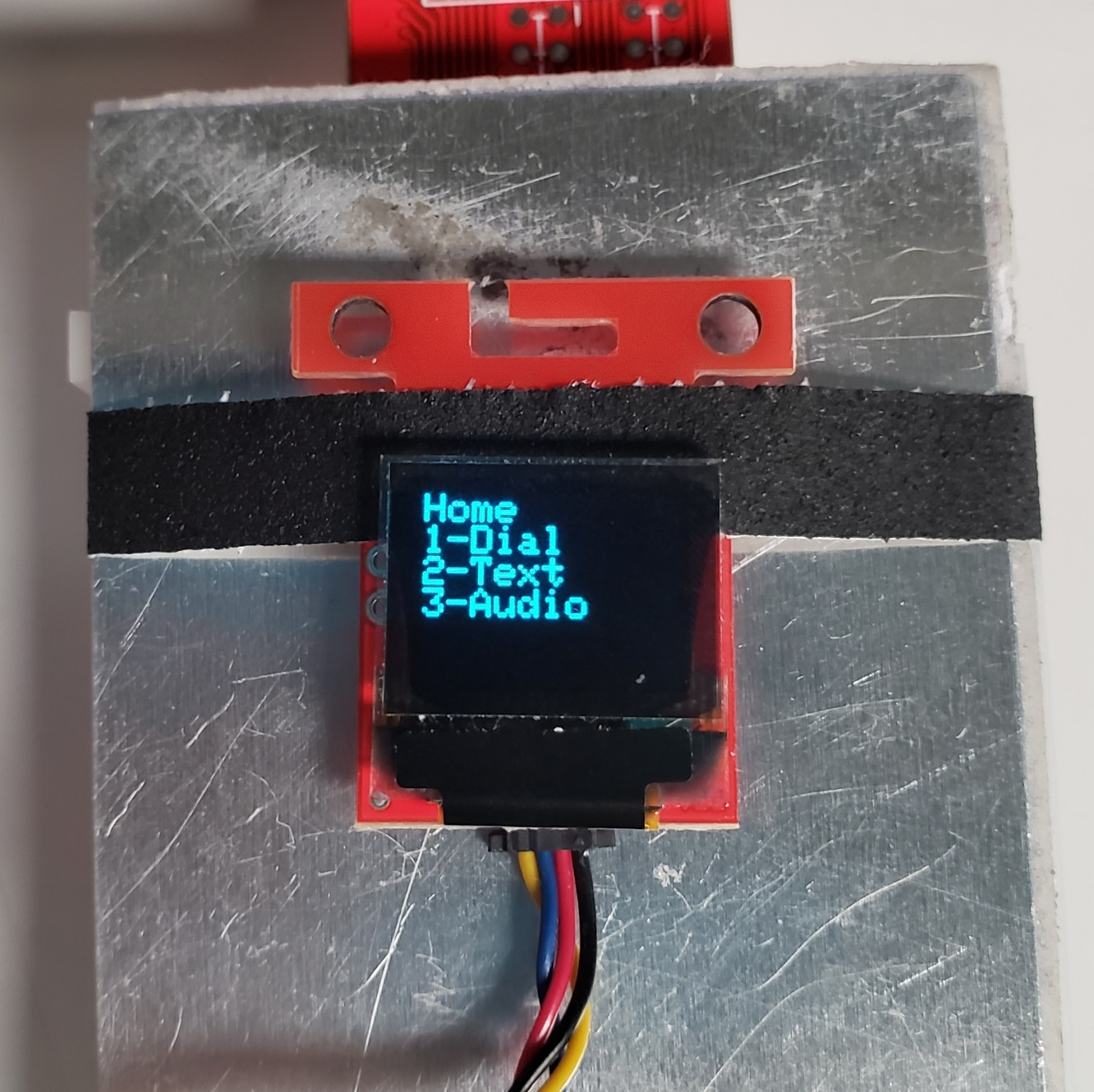
From there, you’ll be able to used the keypad to navigate round and do stuff! Basically, the numbers are for person enter and deciding on sub-menus indicated on the show, the * button will delete enter or return by menus, and the # button is used to complete getting into inputs.
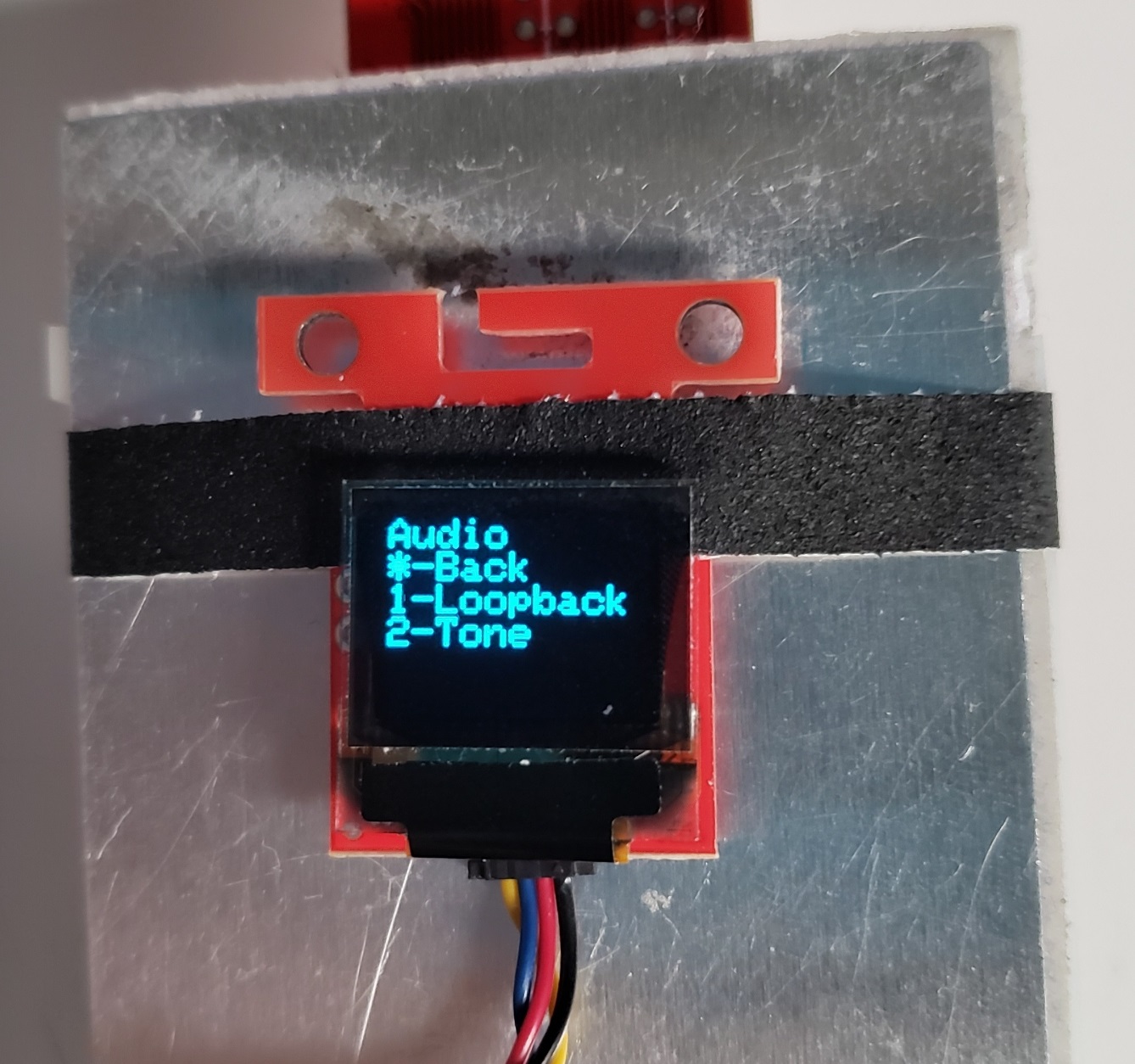
Earlier than diving in although, I might suggest doing a pair issues to confirm every thing is working. First, the code is setup to generate a brief tone by the speaker at any time when a secret is pressed on the keypad. Press any of the keypad buttons, and the speaker ought to play a DTMF tone similar to no matter key was pressed. When you do not hear it, it is best to troubleshoot that earlier than transferring ahead. Test the wires are all going to the fitting spots, and take a look at operating the Arduino examples for the audio codec.
Assuming that works, enter the audio menu and run the loopback take a look at to substantiate whether or not the microphone is working too. Be warned, this takes the microphone output and sends it straight to the speaker, so it should create a number of suggestions and might get very loud in a short time! Urgent the * button ought to cease it, however you can additionally cowl the speaker together with your hand or be able to unplug one thing if wanted. Once more, if this doesn’t work, it is best to troubleshoot it earlier than transferring ahead.
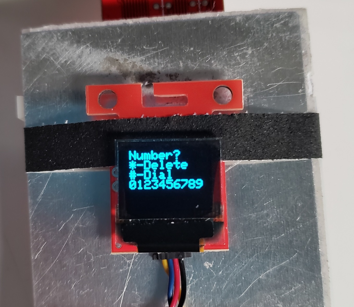
If the loopback take a look at works, then which means just about the entire {hardware} is working appropriately! The final take a look at is to see if you can also make telephone calls. From the principle menu, enter the dial menu, then enter the quantity you need to name. As soon as completed, press the # button to dial the quantity. Assuming all goes effectively, the opposite telephone ought to ring and it is best to be capable of have a dialog with the opposite individual! And you’ll press the * button to finish the decision.
If in case you have any bother making the decision, make sure you strive the audio checks described above, and take a look at among the networking examples from the SparkFun u-blox Mobile Arduino Library. Additionally ensure that your SIM card works with the LARA-R6, and that your knowledge plan assist telephone calls.
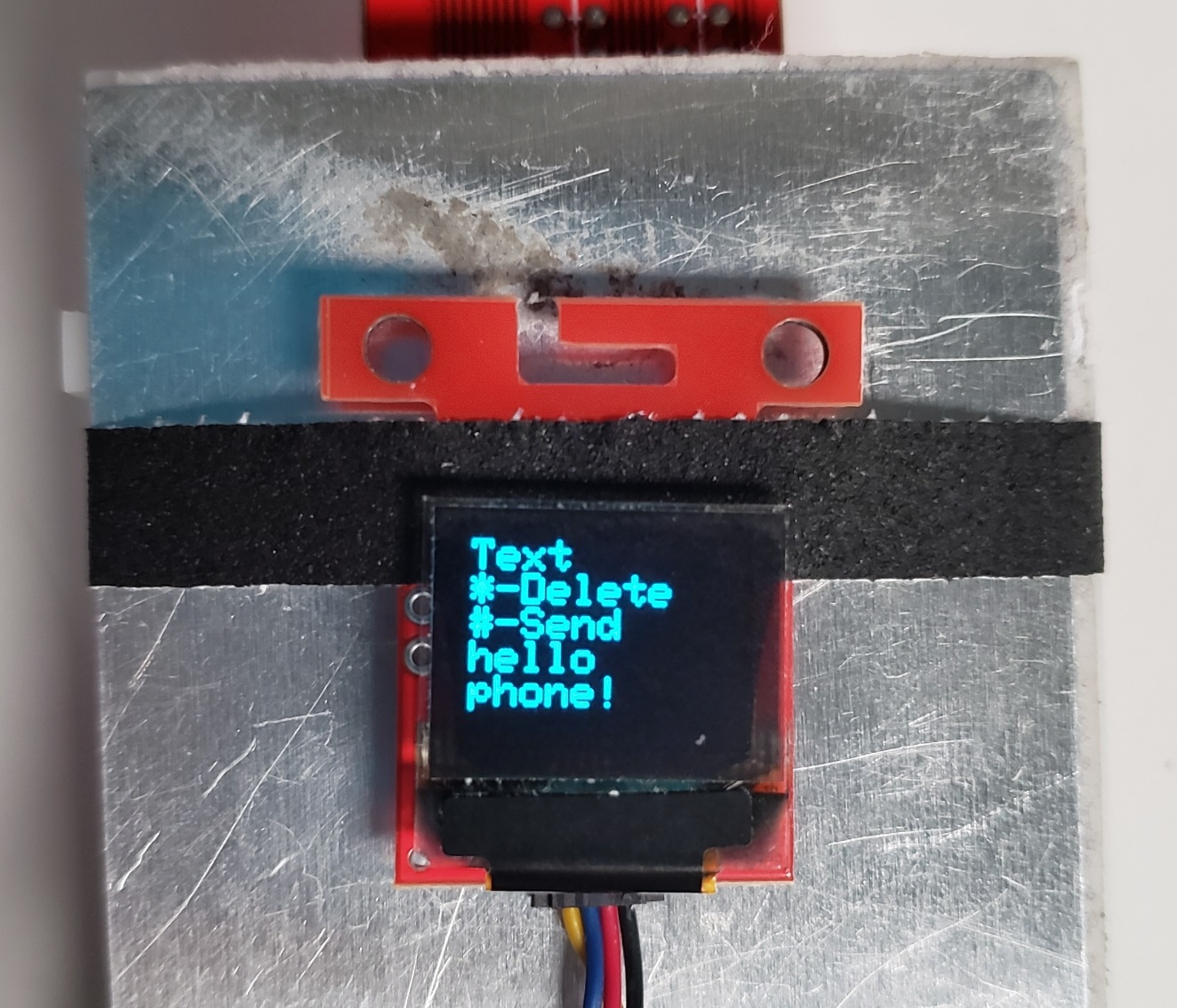
Along with telephone calls, you’ll be able to ship textual content messages! Enter the textual content menu, then enter the message you need to ship. For these acquainted with previous flip telephones, I’ve applied a primitive model of T-9 typing! For these unfamiliar, you press the identical button a number of instances to cycle by 3 or 4 completely different characters (1 is used for punctuation, 2 is used for ABC, 3 is used for DEF, and so on.). Press the * button to delete a personality, or the # button to complete.
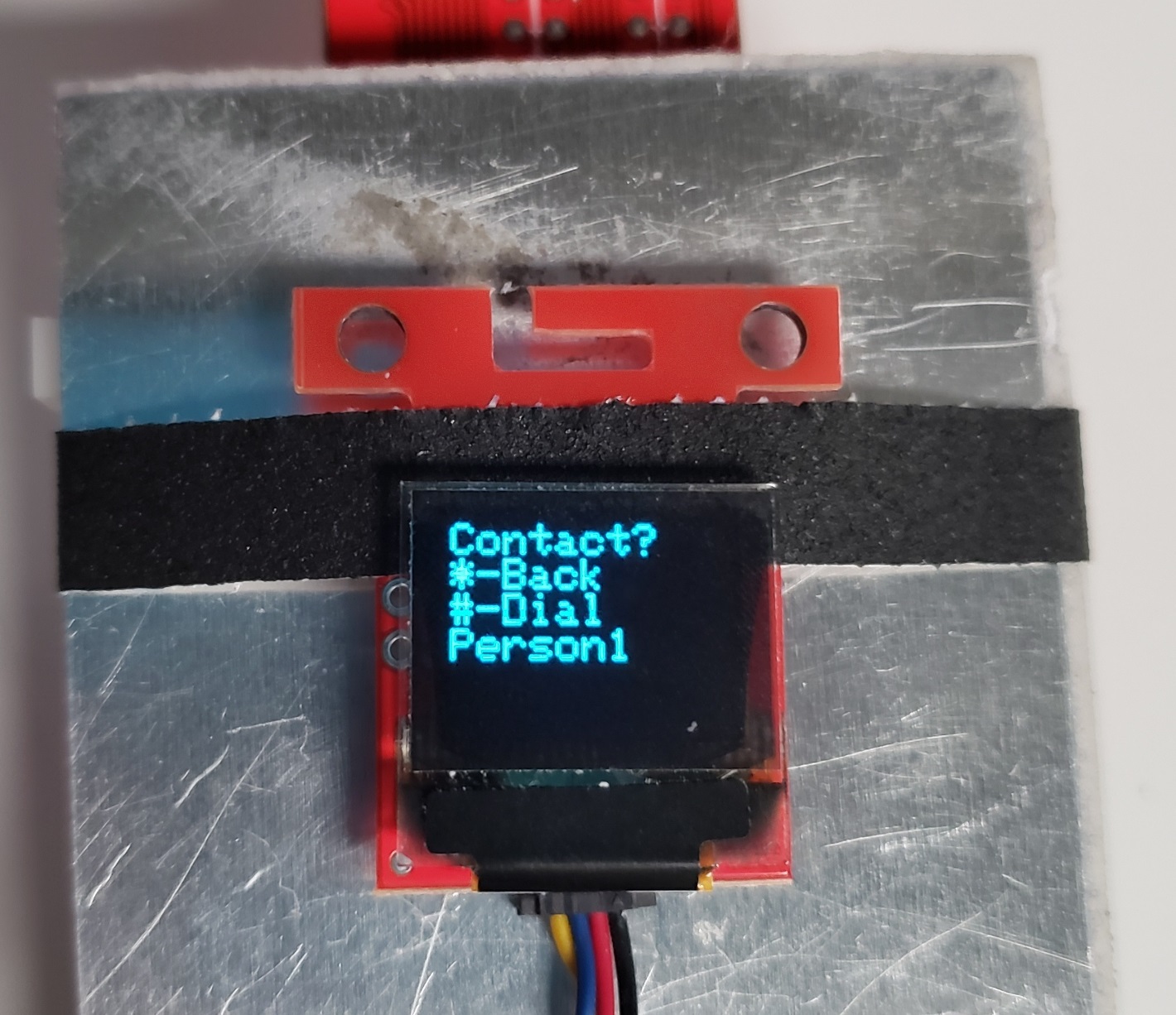
As soon as executed, you’ll be able to then enter the quantity to ship the textual content to, then press the # button once more to ship the textual content. When you get uninterested in getting into individuals’s telephone numbers on a regular basis, you’ll be able to add them to your pace dial contact checklist! I’ve applied this as a part of the Arduino code, so you may have to edit that for this characteristic. Open the Breadboard_Phone_Definitions.h file, and close to the highest is the place you’ll be able to set your contact names and numbers. As soon as executed, re-upload the code and any time you are within the dial menu, press the # key to enter the pace dial menu; every key will correspond to your contact checklist.
The final main characteristic is you could additionally obtain telephone calls, however that is concerning the extent of what I applied. Like I stated, there’s undoubtedly quite a few options absent, equivalent to receiving textual content messages. When you select to do that undertaking your self, I might love to listen to the way it goes for you and whether or not you broaden on my current implementation!